Although the current shunt resistor provides precise real-time current measurement and aids designers with multiple benefits – its limitations hinder its application in high-voltage systems.
Current sensing technology plays a crucial role in various industries, where accurate and reliable measurements are essential for optimizing performance and ensuring system efficiency. However, although affordable and accurate, the commonly used shunt resistor lacks galvanic isolation, rendering it unsuitable for high-voltage measurements. This limitation raises concerns about meeting the current sensing needs of applications like 800V battery-powered electric vehicles, 1,500V solar energy systems, 2,000V electric aircraft propulsion systems, and several others.
The market for current sensing technology is projected to reach USD 3.6 billion by 2025, indicating an increasing demand for solutions that can overcome traditional shunt resistors’ limitations and meet modern power systems’ requirements. While alternative technologies like current transformers and magnetometers (Hall-effect and magnetoresistive) have emerged, they often come with limitations in speed, accuracy, size, operational range, and costs. This highlights the growing need for innovative current sensing technologies that combine the precision and affordability of shunt resistors with galvanic isolation, specifically designed to address the challenges posed by high-voltage applications.
Usage of Shunt Resistors
Integrated systems in power electronics bring numerous advantages, such as improved efficiency, enhanced reliability, and simplified design and assembly. As various industries undergo rapid electrification, an increasing demand for integrated systems and modules exists. The emergence of advanced power semiconductors devices like silicon carbide and gallium nitride transistors, known as wide bandgap (WBG) semiconductors, further drives the need for integrated solutions to achieve optimal performance and cost benefits.
One notable advantage of utilizing current shunt technology is its affordability Compared to alternative measurement techniques. the current shunt provides a cost-effective solution without affecting the accuracy of the model/circuit. When integrated with the power module, a less complex and more compact sensing result can be achieved. In practical applications, additional circuitry is typically required to accurately read and interpret the information obtained from the current shunt. This often involves the implementation of amplification and conditioning circuits that magnify the small voltage drop across the shunt and convert it into a measurable signal.
Shunt Resistors and Their Current Sharing Capabilities
The shunt resistors used in the experiment have a guaranteed tolerance of 1% for their resistance values. Additionally, they have a temperature coefficient of less than 50ppm/K relative to 20°C, resulting in a maximum deviation of up to 0.5% at a temperature of 120°C. In the worst-case scenario, it was assumed that all parallel-connected shunt resistors exhibit the maximum deviation simultaneously. The shunt resistors are composed of a resistive alloy connected to copper terminals.
The Seebeck coefficient of this alloy, with respect to copper, is 1μV/K. Considering a temperature difference of 20K across the resistive alloy, an expected voltage error of 20μV is calculated. Considering that the nominal current corresponds to 128.6mV across the country shunt, this voltage error accounts for 0.016% of the nominal current. Hence, the thermoelectric effect has a minor impact.

Simulation results illustrate the effects of inhomogeneous current sharing among the resistors. Figure 1 depicts the simulated DC potential distribution when each bottom IGBT conducts a current of 100A. The simulation shows a voltage drop discrepancy between resistor number 1 and resistor number 7, primarily due to the voltage drop across the DBC resulting from the placement of the IGBTs, shunt resistors, and bond wires.

Figure 2 illustrates the simulated voltages across the individual shunts for an overall current of 1000A, observed in mΩ. The sense terminal voltage closely matches the voltage across resistor number 3, as the sense conductors on the DBC are connected to this resistor. Evaluation of the results indicates a maximum deviation of less than 0.5% between the sense voltage and the ideal voltage.
The simulations highlight the dependence of the effective shunt resistance on the current path within the module, particularly between the upper and lower switch conduction. Possible error mitigation approaches include separate calibrations for each current path or correcting the resistance with fixed values for each branch. The control algorithm can account for the different resistance values through dynamic weighted averaging based on the current duty cycle.
DC and Pulse Measurement Results
The accuracy of the DC current measurement is verified by applying a DC current to the module and measuring the voltage across the sense terminals.
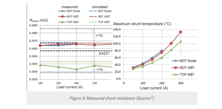
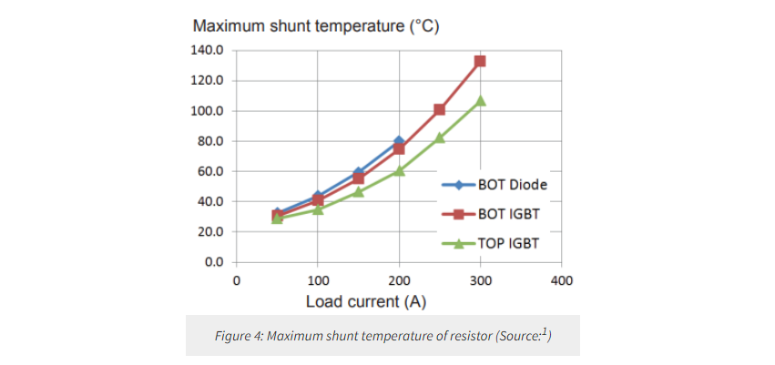
Figure 3 presents the plotted effective shunt resistance RSense against the load current for three conduction paths: bottom diode, bottom IGBT, and top IGBT. As predicted by the simulation, a discernible difference between the upper and lower switches could be observed. The plot also includes the ideal value of 2mΩ/7 and deviations of ±1% as reference. Figure 3 shows no significant temperature dependence of the shunt values, despite the maximum temperature on the shunt resistors increasing with the load current according to Figure 4. The shunt temperatures were measured using an infrared camera in an air-cooled system.
The current measurement’s dynamic characteristics were investigated through pulse measurements. Figure 5 depicts the direction of the current waveform during activation (t=0) and deactivation (t=46.1μs) of the lower switch.

The measurements were conducted under specific conditions, such as a DC link voltage of VDC=600V, a relatively low load inductance of load=35μH, and at room temperature. The black curve in Figure 5 represents the current measured via a sensor connected to the AC terminal. In contrast, the green curve corresponds to the voltage measured across the shunt obtained using a delta-sigma modulator and digital filter with a decimation rate of OSR=64. Additionally, Figure 6 displays the deviation observed in Figure 5 between the current sensor and shunt measurements with the red curve.

The blue curve is generated by considering two corrections: incorporating the simulated shunt resistances of the different current paths and subtracting the influence of inductive coupling LShunt∙di/dt with LShunt=0.4nH. It should be noted that the areas marked by grey boxes in Figure 6 indicate the sections where larger deviations occur due to the low-pass nature of the filter. These deviations emphasize the limitations of the measurement setup and the challenges in accurately determining the inductor Shunt due to transit time errors and the filter’s characteristics.
Conclusion
The current shunt remains a powerful hands-on tool in electrical design, providing high-accuracy current measurement and control. Although there are certain limitations, such as introducing parasitic elements and lacking built-in isolation, these challenges can be addressed through careful design and mitigation techniques. By exploiting its advantages, while at the same time taking care of its limitations, designers and researchers can optimize performance and efficiency in innovative products.
About US
Heisener Electronic is a famous international One Stop Purchasing Service Provider of Electronic Components. Based on the concept of Customer-orientation and Innovation, a good process control system, professional management team, advanced inventory management technology, we can provide one-stop electronic component supporting services that Heisener is the preferred partner for all the enterprises and research institutions.