Power converter control plays a crucial role in optimizing the overall performance of power-conversion systems. With proper control, power converter efficiency can be maximized, energy losses reduced and component life improved. By designing sophisticated control algorithms, power transitions can be managed efficiently and optimally while keeping the power converter output voltage and current constant.
An important aspect of power converter control is the ability to adapt to dynamic variations in load conditions and power-source characteristics. This allows the power converter to provide stable and consistent output, regardless of changes in power demand or environmental conditions. In addition, power converter control can include a number of advanced features, such as output waveform adjustment, harmonic distortion compensation and power quality management. These features make it possible to adapt to the specific needs of the application and ensure a reliable, high-quality power supply.
Research and development in the field of power converter control are continuously leading to new techniques and more sophisticated algorithms. The use of advanced digital controllers, combined with intelligent control algorithms based on machine learning, is opening up new perspectives to further improve the performance of power electronic converters. The pulse-width–modulation (PWM) technique is widely used to control power converters. This control method involves the generation of a signal that manages to switch the power converter’s electronic switches on and off to achieve the desired voltage value at the output. This switching function (see an example in Figure 1) is achieved by comparing two signals: the modulant and the carrier. These two signals can be summarized as follows:
● The modulant is a signal that contains the actual information about the desired output voltage.
● The carrier is a periodic signal, usually in the shape of a triangular wave, whose switching frequency corresponds to that of the power converter.
Through the interaction between these two signals, the switching function is generated. As a demonstration, the system depicted in the figure consists of three types of generators, some real and some calculated and processed:
V(1) is a triangular signal, referred to as “carrier.” It is a periodic and usually fixed-frequency signal. Depending on the needs, its form may be different.
V(2) is a threshold voltage, referred to as “modulating” (or reference voltage). It decides the switching threshold level of the output logic states. It can be chosen by the user or can be of any waveform, such as sinusoidal in the case of operation as an inverter.
V(3) is the switching voltage that is the result of the intersection and comparison of the first two signals. It is called the binary switching function. Usually, if the modulant is greater than the carrier, it will have a value of 1. In the opposite case, it will have a value of 0. The comparison can be performed via hardware, with fast comparison circuits, or via firmware, through the use of powerful microcontrollers.
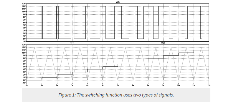
The result of the switching function is sent directly to the driver, which manages the switching on and off of the power converter switches according to the sequence of 1 and 0 of the switching function. As can be seen, therefore, the result is a true PWM signal arising from the presence of two distinct and easily controlled signals. The basic principle of PWM is to vary the pulse width of the switching signal proportionately to the desired reference voltage.
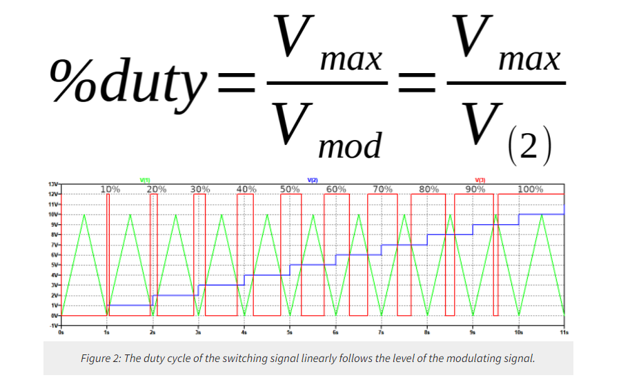
This allows the effective output value of the power converter to be controlled, ensuring proper regulation and high quality of the power signal. The use of PWM, achieved as described above, offers numerous advantages, including high energy efficiency, improved output signal quality, the ability to control output power and reduced power losses. In the example just seen, with respect to the triangular-shaped carrier (see Figure 2), the duty cycle of the output signal linearly follows the level of the modulant, according to the following linear relationship:
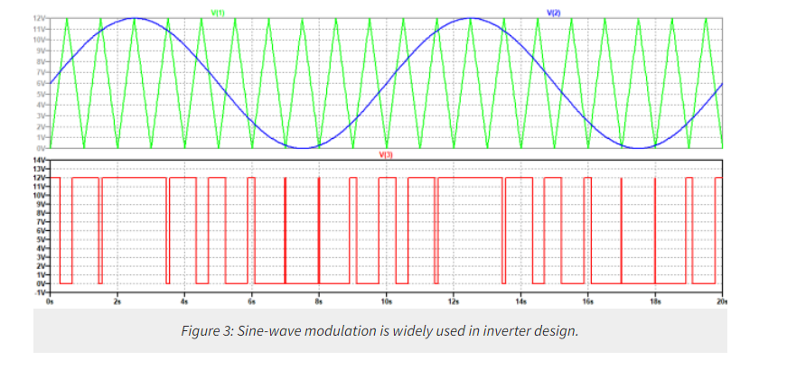
In the case of inverter design, technology is used to generate a pure sine wave. Figure 3 shows the carrier signal, the modulating signal and the result of comparing the first two. It is important to note that the outgoing signal will be affected, inevitably, by the harmonics of the carrier and modulating signals. To reduce EMI effects, it is necessary to design filters that eliminate or reduce such undesirable elements as much as possible.
Conclusion
The generation of a PWM signal, with the carrier and the modulant, is a fundamental technique for controlling power converters. The generation of the switching function enables precise regulation of the output voltage, providing accurate and efficient control of electronic converters. Understanding the basic principles and applications of this technique is critical for engineers and electrical power experts, contributing to the development of innovative solutions for controlling and optimizing electrical power conversions.
About US
Heisener Electronic is a famous international One Stop Purchasing Service Provider of Electronic Components. Based on the concept of Customer-orientation and Innovation, a good process control system, professional management team, advanced inventory management technology, we can provide one-stop electronic component supporting services that Heisener is the preferred partner for all the enterprises and research institutions.