Railway electrification systems rely on a steady DC supply to both power their DC motors and the control/energy circuits. These DC-traction systems are more energy efficient than their coal, gas,or diesel-based counterparts while also reducing CO2 emissions. DC-to-DC converters play a crucial role in improving the energy efficiency and power quality of electrified railways. Electronic components used in these applications will be subjected to extremes in temperature, humidity, vibration and mechanical shock. As such, they require a high degree of electrical and structural integrity to be able to withstand these conditions and reliably operate.
This article explores the requirements for DC-to-DC converters in railway systems, including a general description of DC railways, how DC-to-DC converters are used in these systems, and the standards that allow these devices to function regardless of operating conditions.
A look at DC electric railway systems
Early railway electrification systems were based on low-voltage DC where the supply was provided by diode rectifiers in traction substations (T15, or Ss) along the track, with power distributed to the train’s motors by relying on a power supply given from the overhead lines and rails. The most common voltages for DC-traction systems are 600V for older tramways and underground systems, 750V systems in newer metro, and 1500V used by more suburban lines. Large 3000V systems are also used in suburban networks.
Trends for DC electric railway systems
There is a general trend for railway systems to steadily increase in voltage and efficiency. The increase in voltage allows for a decrease in current where higher gauge (thinner) cables are sufficient. The lower voltage systems will require a high current level, which lead to thicker overhead-lines and short distances between substations. The increase in energy efficiency reduces both CO2 emissions by reducing the energy consumption of the installation. Energy reuse can also be employed through regenerative braking where the kinetic energy of the rotor is converted into electricity and sent back to the power source.
How DC-to-DC Converters used in railway systems
Regenerative braking relies on the use of a large bidirectional DC-to-DC converter to send power back to the battery bank or energy storage system (ESS) from the DC feeder line. Smaller DC conversion is necessary in modern railways to distribute a continuous supply of power to all electronic devices and subsystems within the coach. These auxiliary systems include higher voltage critical systems such as engine controls, motor drive controls, and braking systems, as well as lower voltage secondary systems including lighting, battery charging, indication lamp, pump, and information displays, and electric door openers.
The conventional solution often involves the use of an input filter, a 3-phase inverter, and a low frequency transformer in order to provide electrical isolation between the overhead line voltage and the auxiliary power supply equipment. Typically, this transformer is large and bulky, adding extra mass to an already space- and weight-constrained application. Instead, isolated DC-to-DC converters can be used to meet the size, weight, and power requirements of modern railway applications. The goal is to convert the high 750V, 1500V, and/or 3000V input voltage to a regulated 24, 28, 36, 48, 72, 96, or 110 volt output.
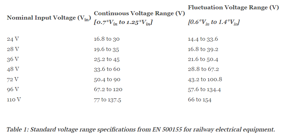
The power distribution within the train from the main supply also requires a chain of DC-to-DC conversion to the secondary systems. As stated earlier, the nominal input voltages can vary from as low as 24 volts to as high as 110 volts; from there, a regulated 3.3, 5, 12, 15, or 24 volt output is necessary. The EN 50155 European standard for railway electrical equipment requires that the nominal input voltage can fluctuate between 0.7 and 1.25 times the rated voltage. The standard also allows short-term deviations between 0.6 and 1.4 times the nominal input voltage.
In other words, a 110V system would require a continuous voltage range between 67.2 volts and 120 volts as was a fluctuation voltage range from 66 volts to 154 volts. DC-to-DC converters can support wide input ranges to cover more than one nominal input voltage. For example, a converter for the common 72V and 110V railway input voltages would need an operating input voltage range from 43.2 volts to 154 volts (see Table 1). P-DUKE offers the RHKW, RHMW, and RHDW series of mountable DC-to-DC converters rated for railway and industrial applications. These devices all offer 3,000 VAC of reinforced isolation as well as a wide input range from 36 volts up to 160 volts, 3,000 VAC of reinforced isolation as well as a wide input range from 36 volts up to 160 volts, allowing them to be used in 72V, 96V and 110V railway applications.
Transformer considerations in isolated converters
Isolated DC-to-DC converters will leverage a transformer to provide galvanic isolation between the input and the output of the device. Typically, the DC-to-DC conversion is accomplished by first translating the signal into AC with an inverter, sending the signal through a transformer, and then through a rectifier for a regulated DC output (so there is no metallic or conductive path between the two parts of the circuit). The amount of isolation is dependent on the clearance and creepage distances, often defined rigorously by the relevant standards. Clearance is the distance through air between two conductors, while creepage is the distance along the surface between two conductors. The clearance distance will prevent arcing, and the creepage distance mitigates the chance a short will occur in the event the surface becomes contaminated and conductive.
The transformer and the number of transformations from DC to AC (and back) will limit the level of efficiency the converter can achieve. The isolation barrier stops the output from being directly controlled for better output regulation. The efficiency of the transformer also has to be taken into account which can limit the efficiency of the converter itself. P-DUKE's patented transformer design enables operation at efficiencies up to 90.5% even with their 4.5 mm clearance and creepage distances (Figure 1).

Meeting the harsh conditions of railway applications
Outside of the EN 50155 standard, the EN61373 standard lists out the test requirements for equipment used in railway vehicles. These devices will be subjected to near-constant vibration and, in some instances, mechanical shock. Tests for vibration will include the simulated long-life testing where the device under test is subjected to at least 15 hours of vibrations at a specific amplitude. For shock testing, the device undergoes a sequence of half sine impulses to reproduce the effects of the transport.
The certifications and safety approvals for electronic equipment used in railway systems span between EN 50155, EN 61373, and EN 44545-2 to ensure these systems performance regardless of electrical, environmental, or fire hazards respectively. Additional standards include the IEC/UL/EN 62368-1 standard for the safety requirements of electrical and electronic equipment in the field of audio, video, information, and communication equipment — systems that are invariably used in railway auxiliary systems.
There are no direct EMI standards for railway applications outside of the EN 50121-2 standard for maximum emission levels measured at the railway boundary fence; however, the electromagnetic environment of these systems are demanding with potential sources from the substations, mains supply, overhead lines, and rolling stock. For both railway and industrial applications, it is beneficial to have a converter that has a level of electromagnetic immunity.
P-DUKE’s Railway DC-to-DC converter offering
P-DUKE’s RHKW (3W/6/10W), RHMW (20W), and RHDW (40W) series DC-to-DC converters are ideal for 72V, 96V, and 110V railway inputs and meet EN 50155, EN 61373, and EN 445545-2 railway standards as well as the IEC/UL/EN 62368-1 standard (with reinforced insulation) for electrical equipment (Figure 2). These converters have built in EMI circuits that are designed according to IEC/EN 55032 class A as well as IEC/EN 50121-3-2. This massively simplifies PCB design and saves board real-estate. The transformer design allows for up to a 90.5% efficiency while also meeting the safety and isolation requirements of both harsh industrial and railway applications. They are tested for vibration and shock with a wide operating temperature from -40°C to +105°C and are operational at 5000 meters for rolling stock that may run through mountainous regions.

Conclusion
DC-to-DC converters used in railway applications have a number of considerations from basic voltage requirements to isolation and construction. This allows these devices to operate regardless of the harsh electrical, mechanical and environmental conditions. Not only do these devices need to meet common railway standards, but should also have a degree of immunity against electromagnetic interference.
About US
Heisener Electronic is a famous international One Stop Purchasing Service Provider of Electronic Components. Based on the concept of Customer-orientation and Innovation, a good process control system, professional management team, advanced inventory management technology, we can provide one-stop electronic component supporting services that Heisener is the preferred partner for all the enterprises and research institutions.